I recently set out to enable VMware ESX(i) 4 Round Robin load balancing with EMC Celerra (CLARiiON) fibre channel storage. Before I get to the details of how I did it, let me preface this discussion with a bit about how I interpret Celerra storage architecture.
The Celerra is built on CLARiiON fibre channel storage and as such, it leverages the benefits and successes CLARiiON has built over the years. I believe most CLARiiON’s are, by default, active/passive arrays from VMware’s perspective. Maybe more accurately stated, all controllers are active, however, each controller has sole ownership of a LUN or set of LUNs. If a host wants access to a LUN, it is preferable to go through the owning controller (the preferred path). Attempts to access a LUN through any other controller than the owning controller will result in a “Trespass” in EMC speak. A Trespass is shift in LUN ownership from one controller to another in order to service an I/O request from a fabric host. When I first saw Trespasses in Navisphere, I was alarmed. I soon learned that they aren’t all that bad in moderation. EMC reports that a Trespass occurs EXTREMELY quickly and in almost all cases will not cause problems. However, as with any array which adopts the LUN ownership model, stacking up enough I/O requests which force a race condition between controllers for LUN access, will cause a condition known as thrashing. Thrashing causes storage latency and queuing as controllers play tug of war for LUN access. This is why it is important for ESX hosts, which share LUN access, to consistently access LUNs via the same controller path.
As I said, the LUN ownership model above is the “out-of-box” configuration for the Celerra, also known as Failover Mode 1 in EMC Navisphere. The LUN path going through the owning controller will be the Active path from a VMware perspective. Other paths will be Standby. This is true for both MRU and Fixed path selection policies. What I needed to know was how to enable Round Robin path selection in VMware. Choosing Round Robin in the vSphere Client is easy enough, however, there’s more to it than that because the Celerra is still operating in Failover Mode 1 where I/O can only go through the owning controller.
So the first step in this process is to read the CLARiiON/VMware Applied Technology Guide which says I need to change the Failover Mode of the Celerra from 1 to 4 using Navisphere (FLARE release 28 version 04.28.000.5.704 or later may be required). A value of 4 tells the CLARiiON to switch to the ALUA (Asymmetric Logical Unit Access or Active/Active) mode. In this mode, the controller/LUN ownership model still exists, however, instead of transferring ownership of the LUN to the other controller with a Trespass, LUN access is allowed through the non-owning controller. The I/O is passed by the non-owning controller to the owning controller via the backplane and then to the LUN. In this configuration, both controllers are Active and can be used to access a LUN without causing ownership contention or thrashing. It’s worth mentioning right now that although both controllers are active, the Celerra will report to ESX the owning controller as the optimal path, and the non-owning controller as the non-optimal path. This information will be key a little later on. Each ESX host needs to be configured for Failover Mode 4 in Navisphere. The easiest way to do this is to run the Failover Setup Wizard. Repeat the process for each ESX host. One problem I ran into here is that after making the configuration change, each host and HBA still showed a Failover Mode of 1 in the Navisphere GUI. It was as if the Failover Setup Wizard steps were not persisting. I failed to accept this so I installed the Navisphere CLI and verified each host with the following command:
naviseccli -h <SPA_IP_ADDRESS> port -list –all
Output showed that Failover Mode 4 was configured:
Information about each HBA:
HBA UID: 20:00:00:00:C9:8F:C8:C4:10:00:00:00:C9:8F:C8:C4
Server Name: lando.boche.mcse
Server IP Address: 192.168.110.5
HBA Model Description:
HBA Vendor Description: VMware ESX 4.0.0
HBA Device Driver Name:
Information about each port of this HBA:�
SP Name: SP A
SP Port ID: 2
HBA Devicename: naa.50060160c4602f4a50060160c4602f4a
Trusted: NO
Logged In: YES
Source ID: 66560
Defined: YES
Initiator Type: 3
StorageGroup Name: DL385_G2
ArrayCommPath: 1
Failover mode: 4
Unit serial number: Array
Unfortunately, the CLARiiON/VMware Applied Technology Guide didn’t give me the remaining information I needed to actually get ALUA and Round Robin working. So I turned to social networking and my circle of VMware and EMC storage experts on Twitter. They put me on to the fact that I needed to configure SATP for VMW_SATP_ALUA_CX, something I wasn’t familiar with yet.
So the next step is a multistep procedure to configure the Pluggable Storage Architecture on the ESX hosts. More specifically, SATP (Storage Array Type Plugin) and the PSP (Path Selection Plugin), in that order. Duncan Epping provides a good foundation for PSA which can be learned here.
Configuring the SATP tells the PSA what type of array we’re using, and more accurately, what failover mode the array is running. In this case, I needed to configure the SATP for each LUN to VMW_SATP_ALUA_CX which is the EMC CLARiiON (CX series) running in ALUA mode (active/active failover mode 4). The command to do this must be issued on each ESX host in the cluster for each active/active LUN and is as follows:
#set SATP
esxcli nmp satp setconfig –config VMW_SATP_ALUA_CX –device naa.50060160c4602f4a50060160c4602f4a
esxcli nmp satp setconfig –config VMW_SATP_ALUA_CX –device naa.60060160ec242700be1a7ec7a208df11
esxcli nmp satp setconfig –config VMW_SATP_ALUA_CX –device naa.60060160ec242700bf1a7ec7a208df11
esxcli nmp satp setconfig –config VMW_SATP_ALUA_CX –device naa.60060160ec2427001cac9740a308df11
esxcli nmp satp setconfig –config VMW_SATP_ALUA_CX –device naa.60060160ec2427001dac9740a308df11
The devices you see above can be found in the vSphere Client when looking at the HBA devices discovered. You can also find devices with the following command on the ESX Service Console:
esxcli nmp device list
I found that changing the SATP requires a host reboot for the change to take effect (thank you Scott Lowe). After the host is rebooted, the same command used above should reflect that the SATP has been set correctly:
esxcli nmp device list
Results in:
naa.60060160ec2427001dac9740a308df11
Device Display Name: DGC Fibre Channel Disk (naa.60060160ec2427001dac9740a308df11)
Storage Array Type: VMW_SATP_ALUA_CX
Storage Array Type Device Config: {navireg=on, ipfilter=on}{implicit_support=on;explicit_ow=on;alua_followover=on;{TPG_id=1,TPG_state=ANO}{TPG_id=2,TPG_state=AO}}
Path Selection Policy: VMW_PSP_FIXED
Path Selection Policy Device Config: {policy=rr,iops=1000,bytes=10485760,useANO=0;lastPat=0,numBytesPending=0}
Working Paths: vmhba1:C0:T0:L61
Once the SATP is set, it is time to configure the PSP for each LUN to Round Robin. You can do this via the vSphere Client, or you can issue the commands at the Service Console:
#set PSP per device
esxcli nmp psp setconfig –config VMW_PSP_RR –device naa.60060160ec242700be1a7ec7a208df11
esxcli nmp psp setconfig –config VMW_PSP_RR –device naa.60060160ec242700bf1a7ec7a208df11
esxcli nmp psp setconfig –config VMW_PSP_RR –device naa.60060160ec2427001cac9740a308df11
esxcli nmp psp setconfig –config VMW_PSP_RR –device naa.60060160ec2427001dac9740a308df11
#set PSP for device
esxcli nmp device setpolicy –psp VMW_PSP_RR –device naa.50060160c4602f4a50060160c4602f4a
esxcli nmp device setpolicy –psp VMW_PSP_RR –device naa.60060160ec242700be1a7ec7a208df11
esxcli nmp device setpolicy –psp VMW_PSP_RR –device naa.60060160ec242700bf1a7ec7a208df11
esxcli nmp device setpolicy –psp VMW_PSP_RR –device naa.60060160ec2427001cac9740a308df11
esxcli nmp device setpolicy –psp VMW_PSP_RR –device naa.60060160ec2427001dac9740a308df11
Once again, running the command:
esxcli nmp device list
Now results in:
naa.60060160ec2427001dac9740a308df11
Device Display Name: DGC Fibre Channel Disk (naa.60060160ec2427001dac9740a308df11)
Storage Array Type: VMW_SATP_ALUA_CX
Storage Array Type Device Config: {navireg=on, ipfilter=on}{implicit_support=on;explicit_ow=on;alua_followover=on;{TPG_id=1,TPG_state=ANO}{TPG_id=2,TPG_state=AO}}
Path Selection Policy: VMW_PSP_RR
Path Selection Policy Device Config: {policy=rr,iops=1000,bytes=10485760,useANO=0;lastPat=0,numBytesPending=0}
Working Paths: vmhba1:C0:T0:L61
Notice the Path Selection Policy has now changed to Round Robin.
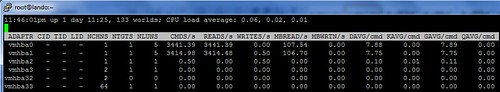
I’m good to go, right? Wrong. I struggled with this last bit for a while. Using ESXTOP and IOMETER, I could see that I/O was still only going down one path instead of two. Then I remembered something Duncan Epping had said to me in an earlier conversation a few days ago. He mentioned something about the array reporting optimal and non-optimal paths to the PSA. I printed out a copy of the Storage Path and Storage Plugin Management with esxcli document from VMware and took it to lunch with me. The answer was buried on page 88. The nmp roundrobin setting useANO is configured by default to 0 which means unoptimized paths reported by the array will not be included in Round Robin path selection unless optimized paths become unavailable. Remember I said early on that unoptimized and optimized paths reported by the array would be a key piece of information. We can see this in action by looking at the device list above. The very last line shows working paths, and only one path is listed for Round Robin use – the optimized path reported by the array. The fix here is to issue the following command, again on each host for all LUNs in the configuration:
#use non-optimal paths for Round Robin
esxcli nmp roundrobin setconfig –useANO 1 –device naa.50060160c4602f4a50060160c4602f4a
esxcli nmp roundrobin setconfig –useANO 1 –device naa.60060160ec242700be1a7ec7a208df11
esxcli nmp roundrobin setconfig –useANO 1 –device naa.60060160ec242700bf1a7ec7a208df11
esxcli nmp roundrobin setconfig –useANO 1 –device naa.60060160ec2427001cac9740a308df11
esxcli nmp roundrobin setconfig –useANO 1 –device naa.60060160ec2427001dac9740a308df11
Once again, running the command:
esxcli nmp device list
Now results in:
naa.60060160ec2427001dac9740a308df11
Device Display Name: DGC Fibre Channel Disk (naa.60060160ec2427001dac9740a308df11)
Storage Array Type: VMW_SATP_ALUA_CX
Storage Array Type Device Config: {navireg=on, ipfilter=on}{implicit_support=on;explicit_support=on;explicit_allow=on;alua_followover=on;{TPG_id=1,TPG_state=ANO}
TPG_id=2,TPG_state=AO}}
Path Selection Policy: VMW_PSP_RR
Path Selection Policy Device Config: {policy=rr,iops=1000,bytes=10485760,useANO=1;lastPathIndex=1: NumIOsPending=0,numBytesPending=0}
Working Paths: vmhba0:C0:T0:L61, vmhba1:C0:T0:L61
Notice the change in useANO which now reflects a value of 1. In addition, I now have two Working Paths – an optimized path and an unoptimized path.
I fired up ESXTOP and IOMETER which now showed a flurry of I/O traversing both paths. I kid you not, it was a Clark Griswold moment when all the Christmas lights on the house finally worked.
So it took a while to figure this out but with some reading and the help of experts, I finally got it, and I was extremely jazzed. What would have helped was if VMware’s PSA was more plug and play with various array types. For instance, why can’t PSA recognize ALUA on the CLARiiON and automatically configure SATP for VMW_SATP_ALUA_CX? Why is a reboot required for an SATP change? PSA configuration in the vSphere client might have also been convenient but I recognize has diminishing returns or practical use with a large amount of hosts and/or LUNs to configure. Scripting and CLI is the way to go for consistency and automation reasons or how about PSA configuration via Host Profiles?
I felt a little betrayed and confused by the Navisphere GUI reflecting Failover Mode 1 after several attempts to change it to 4. I was looking at host connectivity status. Was I looking in the wrong place?
Lastly, end to end documentation on how to configure Round Robin would have helped a lot. EMC got me part of the way there with the CLARiiON/VMware Applied Technology Guide document, but left me hanging, making no mention of the PSA configuration needed. I’m getting that the end game for EMC multipathing today is PowerPath, which is fine – I’ll get to that, but I really wanted to do some testing with native Round Robin first, if for no other reason to establish a baseline to compare PowerPath to once I get there.
Thanks again to the people I leaned on to help me through this. It was the usual crew who can always be counted on.


Jason,
Awesome article. I have never had to enable round-robin on Celerra but now if I have to it will be a piece of cake.
In what workload situations would you recommend enabling ALUA and RR LB?
Great article Jason!
Still not sure why you don’t have 4 paths with two optimal and two non-optimal. This way you don’t need to force RR to use a non-optimal path which will increase latency.
Hi Jason, not sure if I completely understand this:
Should the storage array not report more then one optimal path? Or do you only have two paths?
And does enabling the use of non-optimal paths not defeat the whole idea of ALUA?
@Wim & @Duncan
What I have set up is 2 fabrics.
Comprised of 2 HBAs, 2 FC switches, and 2 SP ports on the storage. This provides only 2 paths from host to storage:
VMHBA0 Fabric A switch SPA
VMHBA1 Fabric B switch SPB
Multiple fabrics is a valid HA configuration which eliminates a single point of failure in the fabric itself. I used this configuration for many years at my previous employer.
What you guys are talking about is a single fabric configuration with an ISL between the two switches, which would give me 4 paths and look like the following:
VMHBA0 X Fabric A switch SPA
VMHBA1 X Fabric A switch SPB
This is also a valid configuration but no longer provides a HA failover fabric. There is just one SPOF fabric and an array of possible human errors performed on the FC switches could bring the entire fabric down and all the hosts and storage along with it – a resume updating event. Things that can disrupt a fabric are Zone merge conflict, zone name conflict, domain ID conflict, zoning error, etc.
would it be better to integrate with EMC powerpath VS round robin with the failover mode 4 enable in the navisphere as you mentioned? Just wondering about this.
I think they’re talking about the standard practice of attaching a port from each SP into each fabric.
Switch 1 (fabric A) – SPA port 1
Switch 1 (fabric A) – SPB port 1
Switch 2 (fabric B) – SPA port 2
Switch 2 (fabric B) – SPB port 2
Hosts are zoned to see both SP’s from either fabric. The end result is that hosts have an optimized path across each HBA (and fabric) instead of passing i/o through the SP that doesn’t own the LUN.
Great article, I’m glad you were able to get things working. I’d like to make 2 points
1) The lines where you do:
esxcli nmp satp setconfig –config VMW_SATP_ALUA_CX –device naa.50060160c4602f4a50060160c4602f4a
should not be needed. Those lines should actually be returning an error message. This command is used to give a per-device configuration string to the already configured SATP. In this case the SATP should rejecting the configuration string, though it may be doing so silently.
The SATP is actually selected based on the matching rules in : “esxcli nmp satp listrules”
I suspect the reboot worked because you actually changed the array properties, which caused the SATP rules to recognize the new device state and apply the correct SATP. In the specific case you’re using VMW_SATP_ALUA_CX is applied when the device vendor string matches “DGC” and the array reports tpgs_on. If the array doesn’t report tpgs_on it’ll default to VMW_SATP_CX. My guess is the modifications you made to the array actually flipped the state of tpgs causing the right SATP to be applied.
2) SATP changes do require a restart to apply in the general case. However if there is no I/O going down the paths to those devices and there are no active VMFS volumes mounted you can try:
esxcli corestorage claiming reclaim –device
This will attempt to unregister the device with the VMkernel and immediately re-register it. The re-registration process will re-run the SATP matching rules and would result in your device getting claimed by the correct SATP. This can and does fail if the VMkernel things any of the paths are in use, but if you’re not on a production system with active VMs you can try it out for your testing.
Hope that helps.
Something else not yet mentioned is the option to set your desired path selection policy of round-robin prior to presenting LUNs.
esxcli nmp satp setdefaultpsp –psp VMW_PSP_RR –satp VMW_SATP_ALUA_CX
As LUNs are discovered they will automatically use round-robin.
Great job Jason. Thanks for taking the time to cull all this information and post it here. I wish EMC would put together a short best practices guide for setting this up; I know at least one other storage vendor already has.
One thing I wanted to question was the activation of the non-optimzed path. In that other vendor’s guide (OK, it’s HP: http://tinyurl.com/yen2p2m) they state that a non-optimal path will only be used if no optimal paths exist. But they mention that it may be suitable (to set the useANO=1 option) for write-intensive environments.
Then I found the EMC CLARiiON ALUA – A Detailed Review white paper: http://tinyurl.com/ye7v2p9. There they recommend that you only use the active-optimal path to avoid a negative performance impact. It also states that PowerPath does this by default.
So I’m thinking that it may not be best to enable the useANO option unless you have a very specific reason to, such as yours where you have just 2 paths.
Lastly, have you done any testing with the “iops” round robin nmp setting? Again, the HP guide recommends setting this to 1. I can’t find anything in EMC documentation. Chad over at VirtualGeek (http://tinyurl.com/y9pemwa) recommends setting this to 1 for iSCSI. Any recommendations on setting this option for the CLARiiON using 4Gbps fiber?
Lastly (sorry for the long post), it looks like there may be a bug and the iops configuration setting may not survive a reboot: http://tinyurl.com/y9wplp8
@Rich I did indeed do some testing with iops=1 policy and sent the result to Duncan Epping to blog. He is busy this week at Partner Exchange in Las Vegas. Maybe he will put something out next week if/when he recovers.
I’m kind of surprised to read that SATP is not detected automatically. In fact it is NMP’s function to detect array type and apply specific SATP. either i have not understood correctly or something is wrong in NMP. NMP must detect the array type. i.e what
esxcli nmp satp list –signifies.
Many thanks for this post. I believe Round Robin is not better without PowerPath VE, in fact Active/Active best and reliably if you have high consolidation ratio.
@Techstarts In my testing, I would agree with Kevin K. The SATP properly detected the CLARiiON in ALUA mode. But, it did not do so when I just changed the Failover Mode for the host. I had to unpresent and represent the LUN to have it detected. I’m guessing, as Kevin K. mentioned, that the evaluation of the rules only happens during the initial scan or at boot.
I’d also like to mention that in my testing, Round Robin provided a significant performance increase over MRU. This was on an HP EVA which is active/active and which ESX sets to MRU by default. I haven’t had an opportunity to compare MRU/RR/PP on the CLARiiON yet.
Thanks Rich, will look forward Active/Active vs RR. I might be able to produce them in few weeks. I’m reading mastering vSphere and that is where my basic understanding is coming from. I read today, if you change the path selection/Load balancing policy to RR(which is not detected automatically), you have to manually set it SATP. Hope it helps.
@Rich I think that was the key difference. The LUNs had already been presented to the ESX hosts prior to configuring them for ALUA afterwards. In this scenario, the host required a reboot to recognize the change. I suppose removing the LUNs and readding them would have also worked, however that was not an option as they contained data and running VMs.
We struggled for days trying to get this to work on a Clariion. After vmware support and EMC support, we needed to go into Navisphere in Engineering mode (ctrl+shift+f12) and check all 4 host initiators as only one was being used. another hidden feature I guess.
Jason. This is awesome. Thank you.
Question. Let’s say you have a mixture of ESX 3.5 U5 and 4.0 U2 hosts (I know its not the most optimal setup, but it’s not my env either), since the 3.5 hosts are not ALUA aware would they still see the array as Active/Passive with Failover mode 4 while the vSphere hosts would see it as Active/Active? Let me know what you think. Thanks!
@Chris
I’m not sure how older versions of ESX would see it but I have the hardware to test that out in the lab. My thought is that it’s not going to be a supported configuration betweeen hypervisor and storage vendor. When I enabled ALUA on the NS-120, it was with the specific knowledge that my hypervisor was ALUA aware and it would be a supported configuration between the two partners. The NS-120 doesn’t ship with ALUA enabled out of the box. The failover mode = 4 configuration change was required by (then) Navisphere to turn on ALUA goodness. The question we are kicking around is how does a non-ALUA aware hypervisor see a non-optimal ALUA path: Is it active, or is it passive? From an array standpoint, it’s active, but non-optimal. My guess is the hypervisor will see 1 active optimal path but will not see the non-optimal path with useANO=0. If useANO=1, then my hunch is ESX will see both paths as active.
Thanks for your post, especially the part with navisphere not showing the correct failover mode. navcli shows failover mode=4 (which is correct), navisphere still shows 1.
Maybe you should point out, that useANO is only necessary when using single targets per initiator. And did you set IOPS=1 finally?
I have a Celerra NS120 and the SP’s are configured active passive. How do I configure iSCSI MPIO (from ESX 4.1) and what will happen in the case of a SP failover?
Second, I keep reading to change the failover mode to 4 to support ALUA. Is ALUA supported with iSCSI MPIO? How and where do I enable failover mode 4 via Unisphere for a Celerra? I’m running Flare 30.
Active/Passive is the recommended configuration for the NS-120. Although you have one server_3 data mover sitting idle, it’s needed for failover in the event the server_2 data mover fails. IIRC the Celerra NS-120 does not support failover or redundancy in an active/active data mover configuration. All of that said, configure your iSCSI target portal(s) on the Celerra. On the ESX/ESXi host side, there are numerous articles which discuss the configuration of multipathing with VMware swISCSI: Create a vSwitch, bind at least 2 vmnics to it, create 2 VMkernel portgroups (vmknics), configure each portgroup to use 1 active vmnic from the vSwitch, and set the other vmnic to not used (don’t configure for standby). Lastly you’d use esxcli in vSphere 4 to bind each portgroup to the swISCSI adapter. With vSphere 5 (released today), this can all be performed via a GUI method.
Hi,
Great article. I just wanted to comment that my findings were similar to what Kevin K suggested (at least for ESX 4.1). Changing the SATP for each device with the esxcli command wasn’t necessary… the host reboot step took care of it.
does this apply for esxi 5?